So yesterday I called Missouri Wind and Solar (they are the folks I got my load divert / charge controller from) to validate my connection set-up. And it's a good thing I did as it turned out I had it wrong. The problem started with conflicting connection instructions that were provided by the company. I tried to follow one set but the referenced numbers were not in existence. So I used the other set and it lacked clear verbiage. So I enlisted a friend whom of which is smarter than I am with electrical stuff and he deduced how the system should be wired by running some tests on a key element, the load divert solenoid. Well... he deduced wrong. Nothing was damaged, but the batteries were getting no charge by the panels as the panels were essentially dead-headed.
Anyhow I got the correct way to wire the panels into the system from the manufacture so I raced home to implement the corrections. Being a "smart" person I first isolated power coming in from the panels so I could make the corrections. Once I was finished and gave the system a good eye-balling I closed the switch to allow the panels to charge the batteries when I heard three distinct loud "clicks"... yup, all three breakers for the panels tripped. Turns out I wired those in backwards. How the hell was I supposed to know how to wire them in!? There was no indication as to which side was hot in, or how current flowed on either the package or the breakers. My friend Rick is the one that pointed out I may have the breakers installed backwards. He was right, they are operational right now and have not tripped yet since I turned them around.
So I learned something else that wasn't obvious... but in the process I thought I had smoked the multi-meter I was loaned/using. I configured the multi-meter to read from the 10A leg so I could see how many Amps each panel was producing. But I forgot to move the probe back to the voltage leg and when I went to test voltage on the batteries **POOF** the smoke got out and the meter stopped working. When I went up to check on the Kill-a-Watt and circuit breakers this morning I noticed the meter was functional again. So apparently I am being given a second chance to melt that fucker!
So today when I get home I will be installing a nice grounding system for my inverter... which is now sitting next to me in my office! Yay! Then I will install the new inverter and if I have time, fix the other issue I have and that is with my Tri-Metric meter. I am just on the edge of the maximum permissible distance for the CAT5 cable I am using to connect my 24V array to the Tri-Metric system. So the solution is to double up the CAT5 which I can do as my friend Rick gave me a spool of the stuff. I hooked it last night but the readings are all funky and the only explanation I can find is that the wire is insufficient diameter to carry the signal correctly. Easy fix for the most part!
The grounding rod is an interesting pickle though... but I think I have a great solution. I have been looking about and it seems that 8ft is the standard depth for a grounding rod. But you can get away with two 4ft rods that are linked together. So I will be looking about the property for some good material to use for a grounding rod set-up. I am questioning the one that is currently in place as I didn't set it and I have no idea how deep it is let alone it's conductive qualities. From what I am reading I can pretty much use just about any conductive piece of steel or metal and I believe we have some re-bar that I can use. I will research the feasibility of using re-bar as a grounding rod before I move forward though.
I am also going to stop by West Marine and pick up some more wire for the new inverter since I will have to mount it differently than I had planned originally. The Trip-Lite 2400W 24V inverter I just got weighs 40lbs so it's nothing like that POS Chinese 3000W 24V inverter I started with. So today is going to be busy and with that I end this entry... soon I will have the main system up and running... and yes, I will post final photos of the system after it's cleaned and installation is completed.
Tuesday, August 14, 2012

Monday, August 13, 2012
Online... mostly!
Okay, so I finally got the 24V system up and running. It took a lot of goading to get the wife on board and help but we did it! The panel mounting system had to be built which is where I needed my wifes help (I will admit it right here... she is a better carpenter than I am, but I rock in the electrical and mechanical world!). Together we built the frame that is being used to support our panels. After the frame was built we then hefted the panels up and I went to work making and testing connections.
The image below is looking up at the solar panels right after we had their initial installations completed and I had connected them to the charge controller. As you can see we used a wood frame made from 4x4's and 2x4's. The panels (I still have to clamp them down) will be clamped to the frame using non-conductive, non-metallic clamps. The entire reason behind using a wood frame was to eliminate several potential issues. The first of which is a possible ground/short condition between the panel frames and support frame. Next is the sheer cost of either buying or building a frame out of metal, and third bi-metallic corrosion is a serious issue that can occur which raises it's own list of issues.
If you look just below the middle panel you will see the combiner box that I put together with all the guts connected. I thought we were going to place the panels up higher on the roof but the wife said no, let's try them here first. So I evaluated the area and agreed it would be perfect for both summer and winter collection. The only issue is an apple tree which we will be trimming soon. Otherwise we are getting excellent performance from the panels where they are right now. The next image is a side view, and there you can see the apple tree I referred to earlier. Also you can see the upper locking board we are using to ensure the panels don't go any where.
One thing about where we live is the wind during the winter months can rip through our property at speeds as high as 80mph in gusts. And that means if it isn't locked,tied, nailed or glued down... it will end up in the neighbors yard. Anyhow the lower frame is metal and we chose to build the connections to the ground out of metal for the strength then we used wood for the upper frame to tie it all together. This weekend I will be installing the ground / lightening arresting system for the panels so as to protect them in storms. We don't get many electrical storms in our area and if we do it's usually one flash of lightening, a big ass boom then a ton of rain.
In the next image is another view of the combiner box. I still have to seal the penetration holes I drilled for my cabling but I am waiting for another couple of weeks while I tweak the system and verify performance. A lesson I learned on my 12V system. The one thing that will happen is the combiner box will be moved to a different location and the lead wires out will be shortened which will increase my efficiency while reducing loss even more. As it is I have already over engineered the system to the point that my theoretical loss is less than 1%. I had a friend who is a retired electrical engineer come up and look at my system, look at my design drawings and specifications and the first thing he said is the way I have it designed and built is that if I see more than a 1% loss he would be surprised.
A bit more on the combiner box, I may have covered this already but I will do it again just for learning purposes. The combiner box it nothing more than an 8x8x4 plastic junction box. I bought two DIN rails and two lugs for the larger cable (4AWG). Then I went to West Marine and bought three 15A DC rated circuit breakers. You're gonna love this, the circuit breakers are held together as a group by a piece of plastic I cut out of a yogurt containers. Then each breaker is wired into the positive leg DIN rail. The solar panels are then each individually connected to a breaker. Now this allows me to isolate panels as needed for what ever reason I may have. It also provides over current protection in the event a panel surges, which I was told can possibly happen in colder weather.
The totals cost for making my own combiner box is around $50-60.00. And it provides the connection point with protection I need plus I have a more intimate knowledge of how my system is put together which allows me the ability to trouble shoot and repair my system much faster.
Okay this next image is the battery house again, with the cheapo inverter I am using for the interim. What you are looking at are 8 USA 6V 380AH batteries configured in a series (24V) parallel set-up that provides a total of 760AH or 18,240W of power potential. Normally this would entail using a 24V inverter as well, BUT since getting said inverter at a price point that I can pay has been proving quite the pain in the ass, I have temporarily set-up a 12V 1500W inverter to run our fridge. It works just fine but the problem is when you do this the two batteries selected drain faster than they charge... I found this out this morning when I was told by my wife that she heard an alarm from the battery house. I didn't hear it until I was 8' away (damn being deaf SUCKS! Or not :-) ) So this morning I had to change the connection points and set up the charger to recharge the two batteries we have been using. Word of advice... don't do it.
 Now before anyone says anything, I am still working on getting things put together so no it's not the best or cleanest looking set-up. But one or two more good weekends and it will look more presentable and be cleaned up. People who know me know I can't stand this kind of mess but... it's a work in progress at the moment.
Now on the inverter issue, I finally resolved this issue this morning. Originally I had ordered this inverter here --> Tripp Lite PowerVerter® Plus 2400W Industrial-Strength Inverter with 2 Outlets from Provantage but due to a comedy of errors (I didn't think it was very fucking funny!) the inverter was back-ordered with no known date of delivery. SO I found the same inverter on Amazon for about $50.00 more but it will be here tomorrow and will be installed tomorrow evening after I get off work.
Now some more really good information I learned. When I started this project I went in with very little knowledge or experience. I didn't know how to really get things going but as I have been moving deeper into the solar / off-grid world I have learned a lot through experience. And one area I made a mistake was in sizing my inverters and my initial system designs. Oh no the system I have is more than capable of doing what I need, but I goofed on my fridge calculations. And I realized that this weekend when I fired my fridge up. In my earlier posts I said 1-1/2 to double the amp rating should be factored in for your fridge or any motor start up. Man... I was not even in the ball park!
So I have a Kenmore refrigerator it was purchase in 2006. Not very old but very efficient! When I was gathering my data for the system design I overlooked how many watts this thing consumed while running. I did the math and according to the math I should be pulling 4.9A at 588W of power... nope! So when this fridge is running it draws 1.69A at 202W and that's for about 10minutes after starting up. Once it's settled down it pulls 1.37A at 164W! For a front load fridge that's 6-8 years old! Not bad! And now that we have insulated it even more, the run times should be reduced. Now back to the area where I screwed up... the start up of this fridge is a whopping 13.8A at 1660W!!! That's to start the fridge! I was WAY off in my estimates. I was also off in my run time consumption. According to the Kill-a-Watt over a 24hr period the fridge burned 2.3kWh of power.
Now looking at the system I have in place I got the solar capacity perfect (it will carry the remainder of my load as well as the fridge) And daily I will be driving my batteries down to an estimated 25% which is perfect! And so long as we have average solar days the system will produce that and more. But the whole point of this particular diatribe is when you are dealing with compressors or high load motors, give yourself about 40-60% for start up demand, the idea is to ensure your inverter can handle a massive current surge without tripping on an over current fault. The reason I say that is an 800W inverter is more than enough to carry my fridge but the startup current exceeds the 800W inverters capacity and so it's a non starter. The 1500W inverter I have right now... it can take the fridge start up but that's it. I can't have any other loads on that inverter.
But tomorrow it won't matter as I will be installing the CORRECT inverter that is designed to handle the load AND work with the system voltage. I think that's all for now, I will make another entry once I have things cleaned up with the system and I have more actual use data. Kill-a-Watt... use them! Serious you can't manage what you can't measure folks.
Okay... here is the system drawing I have with some of the material requirements annotated.

The image below is looking up at the solar panels right after we had their initial installations completed and I had connected them to the charge controller. As you can see we used a wood frame made from 4x4's and 2x4's. The panels (I still have to clamp them down) will be clamped to the frame using non-conductive, non-metallic clamps. The entire reason behind using a wood frame was to eliminate several potential issues. The first of which is a possible ground/short condition between the panel frames and support frame. Next is the sheer cost of either buying or building a frame out of metal, and third bi-metallic corrosion is a serious issue that can occur which raises it's own list of issues.
 |
| 3- 300W / 24V Helios 7T2 panels |
One thing about where we live is the wind during the winter months can rip through our property at speeds as high as 80mph in gusts. And that means if it isn't locked,tied, nailed or glued down... it will end up in the neighbors yard. Anyhow the lower frame is metal and we chose to build the connections to the ground out of metal for the strength then we used wood for the upper frame to tie it all together. This weekend I will be installing the ground / lightening arresting system for the panels so as to protect them in storms. We don't get many electrical storms in our area and if we do it's usually one flash of lightening, a big ass boom then a ton of rain.
 |
| 3- 300W / 24V Helios 7T2 panels side view. |
 |
| Home made combiner box connected and providing power |
The totals cost for making my own combiner box is around $50-60.00. And it provides the connection point with protection I need plus I have a more intimate knowledge of how my system is put together which allows me the ability to trouble shoot and repair my system much faster.
Okay this next image is the battery house again, with the cheapo inverter I am using for the interim. What you are looking at are 8 USA 6V 380AH batteries configured in a series (24V) parallel set-up that provides a total of 760AH or 18,240W of power potential. Normally this would entail using a 24V inverter as well, BUT since getting said inverter at a price point that I can pay has been proving quite the pain in the ass, I have temporarily set-up a 12V 1500W inverter to run our fridge. It works just fine but the problem is when you do this the two batteries selected drain faster than they charge... I found this out this morning when I was told by my wife that she heard an alarm from the battery house. I didn't hear it until I was 8' away (damn being deaf SUCKS! Or not :-) ) So this morning I had to change the connection points and set up the charger to recharge the two batteries we have been using. Word of advice... don't do it.

Now on the inverter issue, I finally resolved this issue this morning. Originally I had ordered this inverter here --> Tripp Lite PowerVerter® Plus 2400W Industrial-Strength Inverter with 2 Outlets from Provantage but due to a comedy of errors (I didn't think it was very fucking funny!) the inverter was back-ordered with no known date of delivery. SO I found the same inverter on Amazon for about $50.00 more but it will be here tomorrow and will be installed tomorrow evening after I get off work.
Now some more really good information I learned. When I started this project I went in with very little knowledge or experience. I didn't know how to really get things going but as I have been moving deeper into the solar / off-grid world I have learned a lot through experience. And one area I made a mistake was in sizing my inverters and my initial system designs. Oh no the system I have is more than capable of doing what I need, but I goofed on my fridge calculations. And I realized that this weekend when I fired my fridge up. In my earlier posts I said 1-1/2 to double the amp rating should be factored in for your fridge or any motor start up. Man... I was not even in the ball park!
So I have a Kenmore refrigerator it was purchase in 2006. Not very old but very efficient! When I was gathering my data for the system design I overlooked how many watts this thing consumed while running. I did the math and according to the math I should be pulling 4.9A at 588W of power... nope! So when this fridge is running it draws 1.69A at 202W and that's for about 10minutes after starting up. Once it's settled down it pulls 1.37A at 164W! For a front load fridge that's 6-8 years old! Not bad! And now that we have insulated it even more, the run times should be reduced. Now back to the area where I screwed up... the start up of this fridge is a whopping 13.8A at 1660W!!! That's to start the fridge! I was WAY off in my estimates. I was also off in my run time consumption. According to the Kill-a-Watt over a 24hr period the fridge burned 2.3kWh of power.
Now looking at the system I have in place I got the solar capacity perfect (it will carry the remainder of my load as well as the fridge) And daily I will be driving my batteries down to an estimated 25% which is perfect! And so long as we have average solar days the system will produce that and more. But the whole point of this particular diatribe is when you are dealing with compressors or high load motors, give yourself about 40-60% for start up demand, the idea is to ensure your inverter can handle a massive current surge without tripping on an over current fault. The reason I say that is an 800W inverter is more than enough to carry my fridge but the startup current exceeds the 800W inverters capacity and so it's a non starter. The 1500W inverter I have right now... it can take the fridge start up but that's it. I can't have any other loads on that inverter.
But tomorrow it won't matter as I will be installing the CORRECT inverter that is designed to handle the load AND work with the system voltage. I think that's all for now, I will make another entry once I have things cleaned up with the system and I have more actual use data. Kill-a-Watt... use them! Serious you can't manage what you can't measure folks.
Okay... here is the system drawing I have with some of the material requirements annotated.

Wednesday, August 1, 2012
24V System Update
We
have movement... finally! So I did exactly what I tell people not to
do and bought cheap... silly me it ended up costing me far more than
money... it's also costing me time and stress. Anyhow currently I
have the majority of my infrastructure in place. The panels will be
mounted soon, the batteries are connected and tested. All I need to
do next is top charge them while I run the fridge and freezer on
generator to drop their temps down till their compressors stop
running.
So
let me back track here a bit and cover WHAT I have on hand right now
and where it came from. Currently I have the following items:
1
– PWM charge controller from Missouri Wind and Sun with a 600W
divert load built in
1
– Dual Pro PS 12/24V 30 A 2 Bank Waterproof Charger # DP15/2
3
– Helios 7T2 300Watt Monocrystaline panels
1
– DYI combiner box
3
– 15A breakers for panels
2
– Isolation switches, one for the panels and one for the inverter
1
– PowerVerter Plus 24V DC Inverter 24VDC-120VAC 2-Outlet Frequency
Control
7
– Custom aluminum battery bus bars
8
– 6V 380AH L16 US Batteries in series parallel for a total of 760AH
capacity
What
is currently installed are the batteries, the charge controller +
divert load, the combiner box, the isolation switches and charger.
Once I get the new inverter I will install the panels on the roof of
the barn shown in the last of the images.
Now
to why I have to wait for a new inverter... simple, I went cheap and
it cost me more in the long run. I knew better but my impatience got
me. Anyhow the 3000W inverter I had purchased was DOA. Well sort of.
It would start intermittently but then just crap out, stop working. I
know I did everything right as I had a couple of folks that actually
do this stuff and that are smarter about electrical stuff than I
check it out. Bottom line, the Chinese POS has been sent back and I
have ordered a Tripp-Lite which should be here either Monday or
Tuesday of next week.
Okay time for some updated photos (well they were up to date when I took them!).
 |
| Battery House - Needs doors still that's this weekend. |
 |
| Charge Controller is in this box I am pointing at |
 |
| This is the 600W divert load. I will need this when the wind turbine is installed |
 |
| The divert load switch if it senses that the batteries are full and power is still coming in it will automatically divert the load. |
 |
| American made! Just in case I don't have enough solar and wind. It does happen although rarely. |
 |
| The batteries with the aluminum interconnects. |
 |
| This is the roof where the panels will go. The space between the closest windows is where my home made combiner box is currently mounted. Once I get the next set of photos up and more installed... well... I'll show ya! |
So
there you have the beginning of the 24V system. And as I wrote
earlier as I move further along I will post updates and photos. Right
now I am estimating a completion date of 11-12 Aug 2012. I hope so
too... tired of waiting and TIRED of the propane fridge!
Tuesday, June 26, 2012
Slowly getting there...
Okay the 3 - 300W Helios 24V monocrystaline panels are in, the 8 - 6V 380AH deep cycle batteries are in, the charge controller with divert load is in, the 3000W 24V pure sine inverter (cheap Chinese brand... if it makes it 2 years I will be happy). Pretty much everything I need is in except the battery terminal connections and a welder so I can manufacture an adjustable rack system for my panels. I found out that the cables I need to run for AC power are already in place!!! Yay for small miracles! So while I have pretty much everything I need... I am once again in a holding pattern. So this is just an quick update to let you know it's coming, real soon with photos to boot!
Peace Love and Five Finger Death Punch!
Peace Love and Five Finger Death Punch!
Friday, March 23, 2012
24VDC system in the making!
Hello!
So it seems that I will in fact be able to move forward with my 24VDC
system in the very near future after all! Of course as things would
be I have to make some changes to how I will proceed but the fact
is... I will very soon be building my new system!!! And yes, I will
post with images the new system as it goes up and comes on line.
This
particular post I will be focusing on a new spreadsheet I have set up
that I would love to share with you that are reading. The idea was to
create a way to track costs and really compare components by cost,
feature and need. The spreadsheet (which I will link to at the bottom
of this post) is essentially a live one that I am using to build my
upcoming 24VDC system. I have a limited budget (yeah... really who
doesn't today!) so I need to put a lot of thought into the items I
purchase and where my money goes.
In
an earlier blog post I mentioned converting my AC refrigerator and
freezer to DC, and this is still going to happen, just not for a
while. The conversion cost is pretty high and while the payback is
reasonable I just don't have the money at the moment to do it. So I
will be using an inverter to run the refrigerator for now. Now
currently I expect the refrigerator to consume about 90AMPS of power
per day. BUT I have a plan to reduce that!
See
the idea is to improve the efficiency with as little cost / effort as
possible. And the only real way I can do this is to improve the
insulation of the current equipment. And since I will have to do this
anyhow for the DC conversion, well I will be just one step ahead! So
the wife and I will add hard foam insulation to the exterior of the
fridge (See
here) then she will put a nice finish exterior over that. I will
admit right here and now my wife is better than I am with finish
carpentry so I do the rough stuff and she does the finish. By adding
the extra insulation and installing it in such a way that is seals
around the gasket area, we will increase the efficiency of the chill
box and reduce the run times of the compressor. This should net us an
estimated 30-40% decrease in power consumption.
And
if it works as I think it will (it's all theory right now) then I can
do the same thing for my deep freezer that I have. And that would be
the bomb diggity right there! So that is really the major change I
have in my current plans.
Now
the planning spreadsheet that I have put together is pretty simple to
use really. And all you have to do is download it and tweak it for
your needs. I was going to use Google docs again but it's a pain in
the ass to take the spreadsheet and recreate it there so I am using a
free file sharing site for now. Anyhow to use it is simple, the areas
that are light gray and have a border around it are where you make
your manual entries. The top portion is called the component pricing
list. Here you enter the component(s), their unit cost (how much each
item costs) the tax rate if applicable and the shipping rate. Keep in
mind this is not accurate and is essentially and estimation form. The
whole idea is to allow you to see how much your components will cost
and plan accordingly.
It
also again will touch on your load requirements and will you meet
them with the items you are selecting. Anyhow the next area in the
components list is the source and URL, where are you planning on
getting this stuff. As you enter items the F, G and H fields will
auto-calculate for you. Then in column|row H12 a total sum will be
auto-calculated. In column|row H13 you enter the amount you have
budgeted and below that the estimated remainder will be
auto-calculated for you.
Now
you will notice that in column|row I14 there is an area that is gray
and had borders, this is where you put the actual remaining amount.
What I mean by that is I will often times start the purchase process
so I can see exactly how much shipping and tax will be and get a
total value. I will then take that total and put it somewhere and add
other actual totals to it. I don't commit the purchase (not until
I am finished shopping and I have the $$ in place!) I simply
close the web page and move to the next item. This is one way to
validate my buying estimations. It's also a way for me to test the
web site if I have never purchased from them before, see if there is
anything that strikes me as odd. Also as an added method of
protection I use a pre-purchased Visa with only $5.00 on it, that way
if it turns out to be a funky site I lose $5.00 and nothing else. By
doing this I can also use a bogus address during the test phase,
again as a way to protect myself and test the site.
Anyhow
the next section is the battery breakdown. By this time you should
have already narrowed you battery choices down to a brand, voltage
and AH rating as well as the configuration you need. This section is
for you to validate your load / run times as well as ensure that when
you start selecting solar panels (and wind turbines as well, hell
even pelton wheels!) you are selecting enough to replenish your
batteries. So you enter the following information, manufacture and
model, voltage, AH Rate, quantity, how many in series (this will give
you your system voltage) and how many sets in parallel to get total
system AH. Once this is done you move to the next section which is
the load!
In
the load section you enter the nomenclature of the item that is the
load, the voltage the amps and how long you think it will run. All of
this information should be readily available from earlier research
you should have done by now. Anyhow this will give you your total
watts, kW and amps requirements. In column|row G26 your total daily
power demand will be auto-calculated, below that you need to enter
what you estimate to be system loss due to inefficiency as well as
line loss. 10% is generally a pretty good number to start with. This
will auto-calculate your total load below and this is what you need
to make up every day with your solar, wind or pelton wheel. Now keep
in mind as I said in earlier posts everything you have is theoretical
you may see better performance or worse performance of your system
and that all depends on weather, temperature, quality of equipment,
quality of connections and installation and just luck of the draw.
All the numbers I have listed assume realistic worse case scenarios
and chances are pretty damn good I will see much better performance
than I show on paper.
When
I ran the numbers for the existing system I have now, they showed far
worse performance that I am seeing. Although the exception to that is
on really cold and cloudy days the system is performing almost
exactly as my worst case scenarios predicted. So I suppose in the end
it's a wash. Now the one thing I didn't do was account for the wind
turbine in my scenario that you will see in the planning spreadsheet.
That is because the wind turbine will not come into significant play
until the winter. Sure right now it will produce power but that is
diminishing as we move into spring. Fall and winter is where I will
see the real production capacity of my wind turbine.
Alrighty
I have rambled enough, the next area is the panel capacity cost
analyzer. This is where you search the web for solar panels that meet
YOUR requirements. I need panels that will charge a 24VDC system so
therefore all my panels that I have selected are rated 24V+. you
really need to get accurate data here... otherwise you could very
well under power you system. Generating more than you need is not a
problem, with a load diverter you don't have to worry. Remember
during the summer you will produce far more than you will consume, if
you designed your system correctly. And during the winter you should
hit on the nose or slightly over with your production to use ratio.
Some will argue this is a poor way to design systems... but then
again those people are also grid tied. I am not so therefore I have
to follow a completely different paradigm than grid tied folks. And
if you are looking to be off grid you will have to follow the same
paradigm I am.
So
with the cost capacity analyzer you will need to enter the panel
manufacture name and model (well you don't have to... but that'll
sure fuck things up for you later!) then what type of panel is it.
Remember monocrystaline is the best! But it's also generally the most
expensive! Next enter the individual panel wattage, volts and amps
(the amps are the most important aspect as they determine actual
charge capacity!) next you enter the panel quantity and the unit cost
(individual cost or if sold as such the pallet cost). Now once you
have done that the sheet will auto-calculate sub-total, tax,
shipping, total cost, total amps and total watts. In the time slot
enter the estimated full sunlight of the shortest solar day of the
year. Again you are planning for the worst return on power. Once you
do that then total amp will auto-calculate which tells you how many
amps you will generate. This is important as you need to replace the
amps you consumed. So the spreadsheet will then auto-calculate the
power balance, in other words it will take your estimation of daily
power consumption and subtract your estimation of power production.
The closer to zero you can get the better. If you go negative then
schweet! The next field you will enter data into os the source / URL
from whence the panels may come.
Now
continuing across the sheet you will see a cost per amp and cost per
watt calculation. The lower the cost per watt the better, but you
knew this already! So what I do is I sort by the actual cost
difference then I look at the power balance and the cost per watt.
Sometimes you will pay more overall but it washes out in the cost per
watt AND you are close to or below zero on your recharge capacity.
And
there ya have it! Play with it and see what you come up with and if
you find an error or have a question as always ask and let me know so
I can correct it.
Link
to the planning spreadsheet:
http://www.4shared.com/office/DKs7vhoI/file.html
Peace,
Love and Five Finger Death Punch!!!
Wednesday, March 14, 2012
New system on the horizon...
Okay,
so I am coming into a bit of money I didn't expect. Which is great!
Sadly though as is the story of my life... it enough to get a good
start but not enough to get it done. Which means I will have to do
things in piece meal again.
But
that's not the reason for this post! No siree Bob! This post is to
talk about a new system I will be building for the cabin and
eventually moving to the main house. If you have read my other posts
you already know what I have in place right now. But this new system
will be a 24VDC system (increase efficiency of the system overall)
with a custom fridge and DC water heating.
I
have been shopping around for a DC refrigerator for some time now and
while I have found some great fridges out there... I can't afford
them! So in my searches I found this link:
And
since I have an AC fridge already as well as the majority of the
materials I need to build with... why not? The great thing is I have
an HVAC technician that is going to help me with sizing the
refrigeration components that work with 24VDC current. The fridge I
have is a 19CuFt. Kenmore so I have to have enough capacity to
maintain 35F. And that's where my friend / co-worker will come in.
right now I am looking at a Dan Foss compressor (actually 2 of them)
one will be set for lead and the other as lag.
More
on the refrigeration set up in a bit, I want to focus on the power
side of the house. So to power this up I will be investing in two
Suntech STP180S-24/Adb+ 180W 24V Solar Panels from the AltE
store. That will give me 360W of power production there. The next
element will be a 600W
24V 7 Blade Raptor Wind Turbine. Since where I live is literally the
prime place for both solar and wind it's a good fit.
The
batteries will be Trojan T105 6V 225AH and I will have a total of 8
set up in series / parallel so I will have a total of 450AH capacity.
And as a load diverter as well as a more efficient means of heating
water I will use a 600W 24VDC hot water heating element. The wind
turbine and the heating element will be purchased from Missouri Wind
and Sun and the batteries will also be purchased from the AltE store.
How
the system will be set up is pretty simple. The wind turbine and
solar panels will be installed to charge the batteries, the how water
element will work as a load diverter in the event I am producing more
power than the batteries can handle. This will prevent the batteries
from being damaged. So my load characteristics will change.
On
top of my existing loads I will be adding my custom made refrigerator
and a hot water heating element. But I will also be adding to my
charging capacity with the wind turbine. Which is perfect as during
the winter months solar is a bit of a bust. But during the summer
it's perfect and wind is minimal. Now the whole reason for using DC
on the refrigeration and water heater is to save money long term.
Right now our current refrigerator is propane fired and only about
7CuFt in size. And one issue we have run into is that when the
propane runs out we sometimes don't notice it until just about
everything is defrosted and warmed up. Not a very healthy or
efficient way of keeping food cool and fresh. The other problem is
the cost of propane is prohibitive! Right now based on my usage
tracking and cost analysis we are spending about $200.00 a month in
propane for refrigeration, heating water, cooking and space heating.
Now that may not seem like a lot to you... but to me, it's too much
especially with times being tight the way they are.
I
figured out that with the DC refrigeration and water heating we will
see a pay-back on our investment in about 28 months. Now that may
seem too long. But in the world of cost efficiency it's not,
especially when you look at the fact that the payback time is when
the system will have paid for itself in propane sales not made. After
the payback period you are ahead. And since the solar panels I have
opted for are rated with a 12-18 year life expectancy I will get far
more production out of them than my payback. Next the wind turbine is
rated to survive about 5 years, again I will see over 2 years of
production AFTER payback has been made. And the life span is
theoretical, it could be longer or it could be shorter (which means
it will take longer to see my payback).
Next
the batteries I have selected are also rated for about 5-7 years, but
with the fact I am always on top of my battery maintenance and the
fact that with the combined sources of power, the batteries will
rarely be driven past 70% which translates to longer life spans.
There are two families close to where I live that are using the same
batteries I will be using and they have both exceeded the life
expectancy of the batteries by 1 year and 19 months respectively. So
again, the payback is well worth it.
Okay
now the home made refrigeration unit. So talking with my HVAC
mechanic I will have to look at the current compressor in my
refrigerator and see what the BTU rating is on the existing AC
compressor then match that to a comparable 24VDC compressor. Right
now we are looking at a Dan Foss BD350GH model 24VDC compressor. We
believe I should be able to use the existing condenser and evaporator
so that will save me some $$$ right there. I will have to get 24VDC
fans for cooling as well as a 24VDC LED for the interior of the
fridge. I can use existing extra wood and insulation we have on our
property to increase the outside insulation aspect of the
refrigerator. This is crucial as it will increase the efficiency of
the system over all and prevent excessive run times on the
compressor.
Hopefully
in my next post I will have the final fridge design and components
list available for anyone that reads this. Peace, Love and Led
Zeppelin!
Monday, February 27, 2012
A visual of my "practice" system!
Okay, so I mentioned earlier that I was going to post up some images of my current system with more data and information. Well I finally got off my ass this weekend and took the required photos.
Now
to reiterate this is a simple system not meant for a full blown home.
I designed it for our cabin one so we could have lights and
entertainment, but also so I could apply what I have been reading
about solar in a practical manner.
I
think the first thing I need to do is one more time list all the various components I
have for both production and load so as to give a more clear image of
what the system I have is doing and to help you the reader understand
the power production use terms in relation to physical objects.
On
the production side we have:
- 3 : Chicago Electric 45W solar kits
- 1 : Sunsaver 20A 12V charge controller
- 2 : Xtreme 12V – 105AH Marine deep cycle batteries
- 1 : TM-2025RV Trimetric meter with enclosure
- 1 : 500A, 50mv shunt
- 1 : Schumacher 15A 12V battery charger
- 1 : Custom combiner box (I took an old breaker box I had and used it).
- 1 : 5kW Honda gasoline generator
On
the load side we have:
- 1 : 40” Sony Bravia LCD tv
- 1 : Sony Bravia 500W home theater with 5.1 surround
- 1 : Thinkpad T61 laptop
- 6 : 5W 12VDC CFL lights
- 1 : TM-2025RV Trimetric meter with enclosure
- 1 : Droid phone (wifes)
On
the load side you are probably wondering why the Trimetric meter
enclosure is on the list. It's simple, the meter has a constant draw
for the display. The amount is tiny (less than .5A) but it's
cumulative and needs to be accounted for. So
now you have the “picture” of both production and load, let's
look at the images and break down what each image means.
First
we start with several images of the Trimetric meter. I have taken 3
photos showing the three most important features that are used daily.
There are several other features I can cover if someone asks.
 |
| Displaying Volts During Solar Charge |
 |
| Showing Amps During Solar Charge |
 |
| Showing Battery Capacity in %age |
Okay the three images above are pretty self explanatory, this is the Trimetric meter and essentially you can think of it as a "Gas Gage" for your battery array. When I took these photos sun light was at the 1030 phase of it's winter angle. During the same day I noticed a peak of 8.4A production. Again this is important as those amps translate to watts. Also the production is from 9 very inexpensive amorphous solar panels. If I had 9 of the more expensive polycrystaline panels I would be seeing somewhere around 25-30A peak production, depending on many factors but we'll cover that much later in the blog.
 |
| Left view of solar panels on balcony |
 |
| Right view of solar panels on balcony |
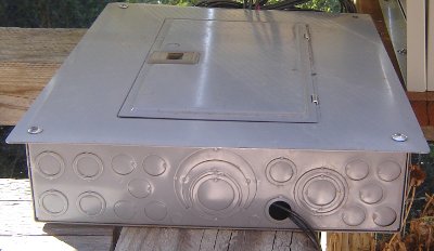
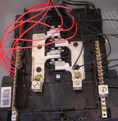
Okay here you can see the 9 amorphous solar panels I have set up on the balcony of our cabin. In the right one you can see the home made combiner box in the shadow. And that leads to the next image!
 |
| External view of combiner box |
 |
| Internal wiring of combiner box |
 |
| Chevy cat inspecting my work... he says it's a go! |
Okay so more information here, essentially I had an old circuit breaker box with the connecting points in storage. It was originally supposed to be used on our house that we are still building but it seems that it's no longer CA code compliant so I re-purposed it for my solar project. Contrary to popular myth you don't have to buy a combiner box, you can make your own by using simple components that are readily available. Many of the items I have access to are reclaimed from older homes or donations through folks that tear homes down for remodeling and such.
Anyhow the combiner box isn't really needed in most cases, but it's a great way to simplify your wiring and to keep things clean. It also cuts down on the amount of wiring you need. In simple terms I have 18 wires that I need to route from the panels to the charge controller. While I don't have a lot of distance in this application, it still made for a mess of wires leading from the panels to the charge controllers, it also meant I had to purchase more wire than I really needed.
With a combiner box you only need two wires for your long run from the panels to the charge controller. If you place it correctly then you can minimize the amount of wire needed to connect your solar panels to your charge controller. In large solar array applications I have seen people use several small combiner boxes that all fed into a master box. This allowed them the ability to isolate banks of panels from production for maintenance, repairs or if they are over producing (common in summer months due to longer charge times) they can reduce their systems production by isolating sections of their panels electrically. I'll cover this in more detail later in the blog.
 | |
| 500A / 50MV SHUNT |
 |
| 500A / 50MV SHUNT with more wire detail and batteries in back |
This shunt pictured above is required for the Trimetric meter system to operate. It essentially prevents the meter from burning up. The wires on the bottom are positive leads and the one on time is a negative lead. I don't have the wiring schematic memorized or with me, but it's pretty simple really and the shunt does come with instructions.
 |
| 12V 800W inverter purchased at O'Reilly's Automotive |

The inverter you see here has only one load cable plugged in and that is strung to the inside of the cabin and connected to a surge protected power strip. Plugged into the power strip is my TV/DVD system, my laptop and my wifes cell phone. The cool thing is we can control the inverter from inside the cabin. And here is how! The positive and negative power leads that connect the inverter to the battery are 8GA wire and they are direct connected to the battery (or maybe it's the shunt... can't remember I will have to update this part later). This provides the current needed for the inverter to function.
We have been running this way for some time now and other than the normal wear and tear on the inverter cooling fans (it wasn't designed for the load cycles we are putting it through) making some noise, it's been flawless in it's performance.
 |
| Sunsaver 12V / 20A solar charge controller |
 |
| Schumacher 120V to 12V / 15A charger on left |
The SunSaver 20 is a replacement charge controller for the 3 charge controllers that came with the Chicago Electric 45W solar kits I am using. The kit controllers worked but were not as efficient as the SunSaver is and they were limited in amp handling capacity so I had to have all three in the battery box and that took up space. Also the SunSaver is designed to assist with maintenance of your batteries. One other bonus with it's 20A capacity I can easily add more panels. All I have to do is mount the new panels then run the leads to the combiner box and viola! More charge capacity! Now I still have one of the original charge controllers in the battery box, but it's now relegated to lighting power provision. You can see it to the right of the SunSaver charge controller behind the inverter.
As you can see by the SunSaver charge controller the wiring is very simple. Two wires from the solar panels via the combiner box, two wires from the batter and two load wires. The load wires are to an additional set of 5 watt lights I have outside the cabin for night illumination.
 |
| 5W 12V CFL light from solar kit |
 |
| My 40" Sony Bravia TV and 500W home theater |
So now we are at the load side. The lights (we have 5 of 6 installed in the cabin and outside) are direct connect to the battery. There is no need for inversion so no loss of power. I will be replacing these lights with LED's this coming pay-day. The outside lights will be upgraded to LED flood lights with only a small power consumption increase.
http://www.led-cfl-lighthouse.com/page/423801738
This flood light above is one of the replacement lights I will be getting. Keep in mind right now the CFL's are rated at 5W and the flood lamp in the link is rated at 4.5W. I will get more lumens per watt as well as better quality lighting and more lighting for outdoors. This is also my foray into 12/24VDC lighting. And it's important I get some experience with this as the house will have 24VDC LED lighting.
The TV/DVD have been performing flawlessly and with the two 105AH batteries in series (that gives me 210AH) we have been able to consistently run them for up to 6 hours without a problem on recharge. The only times as I noted in an earlier post, we have issues with charging is during cloudy days. But even then if we are careful we can run the system for several days before I absolutely have to start the generator.
So there you have it, a visual of my current system. It's not as clean as I would like it BUT by the same token, it works and is very reliable. And with this system I have already made several significant changes to my plans for the larger system. And one of those changes will be the separation of inverted power and direct power. In my old design I was going to take power straight from my master battery array for lighting and refrigeration. But now after seeing how this system is performing and obtaining real world data and experience, I will be building two systems.
The first system will be a 48VDC --> 120VAC system, that will provide the 120VAC power needed for the few appliances we need. The second system will be a 24VDC system and will be the sole source of power for lighting, refrigeration and freezer. Each system needs to be independent of the other for a variety of reasons. The biggest is the DC to AC system will be the most inefficient due to the inversion loss. Also with the location of the 48VDC system it's not practical for me to run secondary DC wiring and then step the voltage down. That adds a layer of complexity that is not needed as well as creates a potential problem with power.
Okay, that's all for now. When I get a chance I will follow-up with the revised system configurations and how I plan to implement them. Till later! Stay free!
Subscribe to:
Posts (Atom)