Okay, so I mentioned earlier that I was going to post up some images of my current system with more data and information. Well I finally got off my ass this weekend and took the required photos.
Now
to reiterate this is a simple system not meant for a full blown home.
I designed it for our cabin one so we could have lights and
entertainment, but also so I could apply what I have been reading
about solar in a practical manner.
I
think the first thing I need to do is one more time list all the various components I
have for both production and load so as to give a more clear image of
what the system I have is doing and to help you the reader understand
the power production use terms in relation to physical objects.
On
the production side we have:
- 3 : Chicago Electric 45W solar kits
- 1 : Sunsaver 20A 12V charge controller
- 2 : Xtreme 12V – 105AH Marine deep cycle batteries
- 1 : TM-2025RV Trimetric meter with enclosure
- 1 : 500A, 50mv shunt
- 1 : Schumacher 15A 12V battery charger
- 1 : Custom combiner box (I took an old breaker box I had and used it).
- 1 : 5kW Honda gasoline generator
On
the load side we have:
- 1 : 40” Sony Bravia LCD tv
- 1 : Sony Bravia 500W home theater with 5.1 surround
- 1 : Thinkpad T61 laptop
- 6 : 5W 12VDC CFL lights
- 1 : TM-2025RV Trimetric meter with enclosure
- 1 : Droid phone (wifes)
On
the load side you are probably wondering why the Trimetric meter
enclosure is on the list. It's simple, the meter has a constant draw
for the display. The amount is tiny (less than .5A) but it's
cumulative and needs to be accounted for. So
now you have the “picture” of both production and load, let's
look at the images and break down what each image means.
First
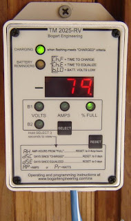
we start with several images of the Trimetric meter. I have taken 3
photos showing the three most important features that are used daily.
There are several other features I can cover if someone asks.
 |
| Displaying Volts During Solar Charge |
 |
| Showing Amps During Solar Charge |
 |
| Showing Battery Capacity in %age |
Okay the three images above are pretty self explanatory, this is the Trimetric meter and essentially you can think of it as a "Gas Gage" for your battery array. When I took these photos sun light was at the 1030 phase of it's winter angle. During the same day I noticed a peak of 8.4A production. Again this is important as those amps translate to watts. Also the production is from 9 very inexpensive amorphous solar panels. If I had 9 of the more expensive polycrystaline panels I would be seeing somewhere around 25-30A peak production, depending on many factors but we'll cover that much later in the blog.
 |
| Left view of solar panels on balcony |
 |
| Right view of solar panels on balcony |
Okay here you can see the 9 amorphous solar panels I have set up on the balcony of our cabin. In the right one you can see the home made combiner box in the shadow. And that leads to the next image!
 |
| External view of combiner box |
 |
| Internal wiring of combiner box |
 |
| Chevy cat inspecting my work... he says it's a go! |
Okay so more information here, essentially I had an old circuit breaker box with the connecting points in storage. It was originally supposed to be used on our house that we are still building but it seems that it's no longer CA code compliant so I re-purposed it for my solar project. Contrary to popular myth you don't have to buy a combiner box, you can make your own by using simple components that are readily available. Many of the items I have access to are reclaimed from older homes or donations through folks that tear homes down for remodeling and such.
Anyhow the combiner box isn't really needed in most cases, but it's a great way to simplify your wiring and to keep things clean. It also cuts down on the amount of wiring you need. In simple terms I have 18 wires that I need to route from the panels to the charge controller. While I don't have a lot of distance in this application, it still made for a mess of wires leading from the panels to the charge controllers, it also meant I had to purchase more wire than I really needed.
With a combiner box you only need two wires for your long run from the panels to the charge controller. If you place it correctly then you can minimize the amount of wire needed to connect your solar panels to your charge controller. In large solar array applications I have seen people use several small combiner boxes that all fed into a master box. This allowed them the ability to isolate banks of panels from production for maintenance, repairs or if they are over producing (common in summer months due to longer charge times) they can reduce their systems production by isolating sections of their panels electrically. I'll cover this in more detail later in the blog.
 | |
| 500A / 50MV SHUNT |
 |
| 500A / 50MV SHUNT with more wire detail and batteries in back |
This shunt pictured above is required for the Trimetric meter system to operate. It essentially prevents the meter from burning up. The wires on the bottom are positive leads and the one on time is a negative lead. I don't have the wiring schematic memorized or with me, but it's pretty simple really and the shunt does come with instructions.
| 12V 800W inverter purchased at O'Reilly's Automotive |
The inverter you see here has only one load cable plugged in and that is strung to the inside of the cabin and connected to a surge protected power strip. Plugged into the power strip is my TV/DVD system, my laptop and my wifes cell phone. The cool thing is we can control the inverter from inside the cabin. And here is how! The positive and negative power leads that connect the inverter to the battery are 8GA wire and they are direct connected to the battery (or maybe it's the shunt... can't remember I will have to update this part later). This provides the current needed for the inverter to function.
We have been running this way for some time now and other than the normal wear and tear on the inverter cooling fans (it wasn't designed for the load cycles we are putting it through) making some noise, it's been flawless in it's performance.
 |
| Sunsaver 12V / 20A solar charge controller |
 |
| Schumacher 120V to 12V / 15A charger on left |
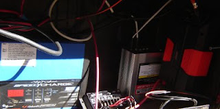
The SunSaver 20 is a replacement charge controller for the 3 charge controllers that came with the Chicago Electric 45W solar kits I am using. The kit controllers worked but were not as efficient as the SunSaver is and they were limited in amp handling capacity so I had to have all three in the battery box and that took up space. Also the SunSaver is designed to assist with maintenance of your batteries. One other bonus with it's 20A capacity I can easily add more panels. All I have to do is mount the new panels then run the leads to the combiner box and viola! More charge capacity! Now I still have one of the original charge controllers in the battery box, but it's now relegated to lighting power provision. You can see it to the right of the SunSaver charge controller behind the inverter.
As you can see by the SunSaver charge controller the wiring is very simple. Two wires from the solar panels via the combiner box, two wires from the batter and two load wires. The load wires are to an additional set of 5 watt lights I have outside the cabin for night illumination.
 |
| 5W 12V CFL light from solar kit |
 |
| My 40" Sony Bravia TV and 500W home theater |
So now we are at the load side. The lights (we have 5 of 6 installed in the cabin and outside) are direct connect to the battery. There is no need for inversion so no loss of power. I will be replacing these lights with LED's this coming pay-day. The outside lights will be upgraded to LED flood lights with only a small power consumption increase.
http://www.led-cfl-lighthouse.com/page/423801738
This flood light above is one of the replacement lights I will be getting. Keep in mind right now the CFL's are rated at 5W and the flood lamp in the link is rated at 4.5W. I will get more lumens per watt as well as better quality lighting and more lighting for outdoors. This is also my foray into 12/24VDC lighting. And it's important I get some experience with this as the house will have 24VDC LED lighting.
The TV/DVD have been performing flawlessly and with the two 105AH batteries in series (that gives me 210AH) we have been able to consistently run them for up to 6 hours without a problem on recharge. The only times as I noted in an earlier post, we have issues with charging is during cloudy days. But even then if we are careful we can run the system for several days before I absolutely have to start the generator.
So there you have it, a visual of my current system. It's not as clean as I would like it BUT by the same token, it works and is very reliable. And with this system I have already made several significant changes to my plans for the larger system. And one of those changes will be the separation of inverted power and direct power. In my old design I was going to take power straight from my master battery array for lighting and refrigeration. But now after seeing how this system is performing and obtaining real world data and experience, I will be building two systems.
The first system will be a 48VDC --> 120VAC system, that will provide the 120VAC power needed for the few appliances we need. The second system will be a 24VDC system and will be the sole source of power for lighting, refrigeration and freezer. Each system needs to be independent of the other for a variety of reasons. The biggest is the DC to AC system will be the most inefficient due to the inversion loss. Also with the location of the 48VDC system it's not practical for me to run secondary DC wiring and then step the voltage down. That adds a layer of complexity that is not needed as well as creates a potential problem with power.
Okay, that's all for now. When I get a chance I will follow-up with the revised system configurations and how I plan to implement them. Till later! Stay free!